All the switches, LEDs, buttons are connected directly to the Raspberry Pi, the AVR micro-controller or through the TM1638 and TM1637boards. More precisely, the push-buttons are connected to the Raspberry Pi, the switches and the potentiometer to the the AVR. All the displays (TM1638 and TM1637) are driven by the AVR.
The following tables regroup all the IO connectiviy. I have choose to name signals as following xxx_yyyzz where:
xxx is the board name or panel number, like RPi (raspberry Pi), 8TMx (TM1638 numbered x), 7TMx (TM1637 numbered x) or Tx/Bx (T for top panel, B for bottom panel)yyy is the button/signal/io name (like GPIO12 or LED)zz is the number (may be empty if not necessary)For buttons and displays, the common valyes for yyy are (some are possible):
SW2: 2-position switch (toggle switch)SW3: 3-position switch (toggle)ROT: rotary switchPOT: potentiometerPB: push buttonLED: led (classical one-color led)RGB: RGB LEDBAR: bargraphDISP: Seven-segment display (block of four)The TM1637 boards are numbered 0 to 2 (so 7TM0 to 7TM2), and the TM1638 boards are numbered 4 to 7 (so 8TM4to 8TM7). Sometimes (in the code), the TM163x are only refered by their number (0 to 7, but there is no board #3). The MSB of their number indicates if they are a TM1637 or a TM1638.
| RPi Pin number | Name | IO | Connected to | Connected to | IO | Name | RPi Pin number | |
|---|---|---|---|---|---|---|---|---|
| 01 (3.3v) | (5v) 02 | |||||||
| 03 (GPIO02, SDA1, I2C) | RPi_IO2 |
In | B8_PB_6 (laser) |
(5v) 04 | ||||
| 05 (GPIO03, SCL1, I2C) | RPi_IO3 |
In | B8_PB_5 (oxygen) |
(GND) 06 | ||||
| 07 (GPIO04, GPIO_GCLK) | RPi_IO4 |
In | B8_PB_0 (rocket E.) |
B8_PB_4 (unhook) |
In | RPi_IO14 |
(TXD0, GPIO14) 08 | |
| 09 (GND) | B8_PB_7 (langing gear) |
RPi_IO15 |
(RXD0, GPIO15) 10 | |||||
| 11 (GPIO17, GPIO_GEN0) | RPi_IO17 |
In | B8_PB_3 (brake) |
B8_PB_1 (spaceship E.) |
In | RPi_IO18 |
(GPIO_GEN1, GPIO18) 12 | |
| 13 (GPIO27, GPIO_GEN2) | RPi_IO27 |
In | B8_PB_2 (parachute) |
(GND) 14 | ||||
| 15 (GPIO22, GPIO_GEN3) | RPi_IO22 |
In | B8_PB_8 (go) |
x | RPi_IO23 |
(GPIO_GEN4, GPIO23) 16 | ||
| 17 (3.3v) | AT_PC0 (IRQ) |
In | RPi_IO24 |
(GPIO_GEN5, GPIO24) 18 | ||||
| 19 (GPIO10, SPI_MOSI) | RPi_MOSI |
Out | AT_MOSI (SPI) |
(GND) 20 | ||||
| 21 (GPIO09, SPI_MISO) | RPi_MISO |
In | AT_MISO (SPI) |
AT_RESET (Reset AT) |
Out | RPi_IO25 |
(GPIO_GEN6, GPIO25) 22 | |
| 23 (GPIO11, SPI_CLK) | RPi_SCK |
Out | AT_SCK (SPI) |
x (SPI Select) | ? | RPi_IO8 |
(SPI_CE0_N, GPIO08) 24 | |
| 25 (GND) | B7_PB_UP (Joystick) |
In | RPi_IO7 |
(SPI_CE1_N, GPIO07) 26 | ||||
| 27 (ID_SD, EEPROM) | (I2C ID EEPROM, ID_SC) 28 | |||||||
| 29 (GPIO05) | RPi_IO5 |
In | B7_PB_DOWN (Joystick) |
(GND) 30 | ||||
| 31 (GPIO06) | RPi_IO6 |
In | B7_PB_RIGHT(Joystick) |
B7_PB_LEFT (Joystick) |
In | RPi_IO12 |
(GPIO12) 32 | |
| 33 (GPIO13) | RPi_IO13 |
x | (GND) 34 | |||||
| 35 (GPIO19) | RPi_IO19 |
x | AT_PC7 and AT_LED |
Out | RPi_IO16 |
(GPIO16) 36 | ||
| 37 (GPIO26) | RPi_IO26 |
x | x | RPi_IO20 |
(GPIO20) 38 | |||
| 39 (GND) | x | REL_SW |
Out | RPi_IO21 |
(GPIO21) 40 |
x: still available
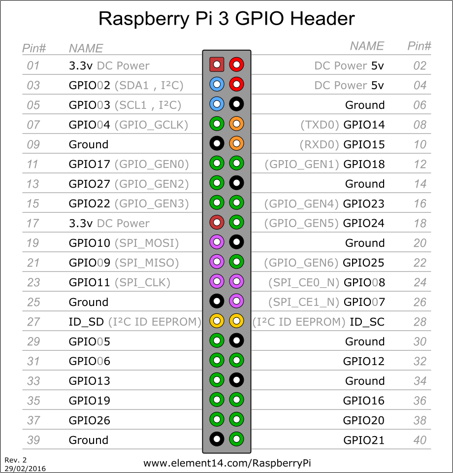
Here is the official Raspberry GPIO table
| RPi USB | Connected to |
|---|---|
| #1 | LCD touchscreen T5_LCD_USB |
| #2 | |
| #3 | USB connector B9_USB_0 |
| #4 | USB connector B9_USB_1 |
HDMI: to the LCD touchscreen T5_LCD_HDMI
3.5 Jack sound: not yet connected
| ATtiny88 Pin number | Name | IO | Connected to | Connected to | IO | Name | ATtiny88 Pin number | |
|---|---|---|---|---|---|---|---|---|
| 01 (PC6, RESET) | AT_RESET |
In | RPi_IO25 |
B4_POT_2 |
Ana | AT_ADC5 |
(ADC5, SCL, PC5) 28 | |
| 02 (PD0) | AT_PD0 |
Out | 7TM0_CLK |
B4_POT_1 |
Ana | AT_ADC4 |
(ADC4, SDA, PC4) 27 | |
| 03 (PD1) | AT_PD1 |
Out | 7TM1_CLK |
B4_POT_0 |
Ana | AT_ADC3 |
(ADC3, SCL, PC3) 26 | |
| 04 (PD2, INT0) | AT_PD2 |
Out | 7TM2_CLK |
B36_SW |
Ana | AT_PC2 |
(ADC2, PC2) 25 | |
| 05 (PD3, INT1) | AT_PD3 |
Out | 8TM4_STB |
B1_SW |
In | AT_PC1 |
(ADC1, PC1) 24 | |
| 06 (PD4, T0) | AT_PD4 |
Out | REL_SW |
RPi_IO24 |
Out | AT_PC0 |
(ADC0, PC0) 23 | |
| 07 (VCC) | 3.3V | GND | (GND) 22 | |||||
| 08 (GND) | GND | AT_LED, RPi_IO16 |
Out | AT_PC7 |
(PC7) 21 | |||
| 09 (PB6, CLKI) | AT_PB6 |
I/O | 8TM_DIO |
+3.3V | (AVCC) 20 | |||
| 10 (PB7) | AT_PB7 |
Out | 8TM_CLK |
Rpi_SCK |
In | AT_SCK |
(SCK, PB5) 19 | |
| 11 (PD5 T1) | AT_PD5 |
Out | 8TM5_STB |
Rpi_MISO |
Out | AT_MISO |
(MISO, PB4) 18 | |
| 12 (PD6, AIN0) | AT_PD6 |
Out | 8TM6_STB |
Rpi_MOSI |
In | AT_MOSI |
(MOSI, PB3) 17 | |
| 13 (PD7 AIN1) | AT_PD7 |
Out | 8TM7_STB |
GND | In | AT_SS |
(SS, PB2) 16 | |
| 14 (PB0, CLK0,ICP1) | AT_PB0 |
Out | 7TM_DATA |
B2_RGB |
Out | AT_PB1 |
(OC1A, PB1) 15 |
For debug purpose only, a simple LED is connected to AT_PC7.
Note that the ATtiny is powered by 3.3V (and not 5V).
There are some 100k resistor between the ATtiny and the RPi for the lines SCK, MISO, MOSI, RESET and SS.
B36_SW regroups the switches B3_SW1, B6_SW1, B6_SW2 and B6_SW3 mounted in a “R-2R ladder”-like.
To be added:
B1_SW (AT_PC1)PD4?)The four TM1638s share the same clock (8TM_CLK) and data I/O (8TM_DIO), to save some GPIO. Only their STB (8TM4_STB to 8TM7_STB) are different:
| Pin description | Name | Connected to |
|---|---|---|
| STB (TM board #4) | 8TM4_STB |
AT_PD3 |
| STB (TM board #5) | 8TM5_STB |
AT_PD5 |
| STB (TM board #6) | 8TM6_STB |
AT_PD6 |
| STB (TM board #7) | 8TM7_STB |
AT_PD7 |
| CLK (Clock input) | 8TM_CLK |
AT_PB7 |
| DIO (Data I/O) | 8TM_DIO |
AT_PB6 |
The following input/output connections can be changed directly in the runMB.py file. This corresponds to my setting, but you can re-arrange the connection as you want (just need to change it in the code)
| TM Board | Output | Connected to | description |
|---|---|---|---|
| #4 | 0 | B4_LED |
autopilot |
| #4 | 1 | B1_LED |
on/off |
| #5 | 0 | T7_LED_1 |
turbo gas |
| #5 | 1 | ||
| #5 | 2 | T8_LED_1 |
light cabin |
| #5 | 3 | T8_LED_2 |
light outisde |
| #5 | 4 | T8_LED_3 |
solar |
| #5 | 5 | T8_LED_4 |
battery |
| #5 | 6 | T8_LED_5 |
fuel cell |
| #5 | 7 | T7_LED_2 |
turbo boost |
The TM1638 IC has three input lines, but we only used the K3 line (the original line used on the board).
| TM Board | Bit | Connected to | Functionality |
|---|---|---|---|
| #4 | 0 | B1_SW3:2 |
Game mode |
| #4 | 1 | B1_SW3:1 |
Game mode |
| #4 | 2 | B5_SW3:2 |
flight mode |
| #4 | 3 | B5_SW3:1 |
flight mode |
| #4 | 4 | B5_SW2 |
autopilot |
| #4 | 5 | B9_SW3:2 |
COM2 |
| #4 | 6 | B9_SW3:1 |
COM1 |
| #4 | 7 | B4_SW2 |
Laser color |
| #5 | 0 | ||
| #5 | 1 | ||
| #5 | 2 | T6_SW3_1:1 |
water pump |
| #5 | 3 | T6_SW3_1:2 |
water pump |
| #5 | 4 | T6_SW3_2:1 |
fuel pump |
| #5 | 5 | T6_SW3_2:2 |
fuel pump |
| #5 | 6 | ||
| #5 | 7 | ||
| #6 | 0 | T8_SW2_5 |
fuel cell |
| #6 | 1 | T8_SW2_4 |
battery |
| #6 | 2 | T8_SW2_3 |
solar |
| #6 | 3 | T8_SW2_6 |
gates |
| #6 | 4 | T8_SW2_2 |
light outside |
| #6 | 5 | T8_SW2_1 |
light cabin |
| #6 | 6 | T7_SW2_2 |
turbo boost |
| #6 | 7 | T7_SW2_1 |
turbo gas |
| #7 | 0 | T9_KB:1 |
Keyboard, line 1 |
| #7 | 1 | T9_KB:2 |
Keyboard, line 2 |
| #7 | 2 | T9_KB:3 |
Keyboard, line 3 |
| #7 | 3 | T9_KB:4 |
Keyboard, line 4 |
| #7 | 4 | do not use | |
| #7 | 5 | do not use | |
| #7 | 6 | do not use | |
| #7 | 7 | do not use |
(the 4 switches B3_SW2_1, B6_SW2_1, B6_SW2_2 and B6_SW2_3 are connected to the ATtiny through the ADC (see this)), and appear to the RPi as connected to pins 4 to 7 of the TM #7).
The last TM1638 board has been “sacrified” to drive the bargraphes and the keyboard. Its second 7-segment display block has been unsoldered, and the bargraphes directly sold on its output (see panel 6).
The three TM1637 have common data (7TM_DATA), but separated clocks (7TM1_CLK, 7TM2_CLK, 7TM2_CLK).
| TM Board | Pin | Name | Connected to |
|---|---|---|---|
| #1, 2, 3 | DATA | 7TM_DATA |
AT_PB0 |
| #1 | CLK | 7TM1_CLK |
AT_PC0 |
| #2 | CLK | 7TM2_CLK |
AT_PC1 |
| #3 | CLK | 7TM3_CLK |
AT_PC2 |